Anatomy of a Video Signal
Overview
You can think of an image as a two-dimensional array of intensity or color data. A camera, however, outputs a one-dimensional stream of analog or digital data. The purpose of the frame grabber is to acquire this data, digitize it if necessary, and organize it properly for transfer across the PCI bus into system memory, from where it can be displayed as an image. In order to understand this process and be capable of troubleshooting display problems, you need to know the exact structure of the video signal being acquired. This document gives an overview of common analog and digital video formats. For information on any non-standard video signal, please refer to the camera manufacturer's documentation.
Table of Contents
Video Scanning
Standard analog video signals are designed to be broadcast and displayed on a television screen. To accomplish this, a scheme specifies how the incoming video signal gets converted to the individual pixel values of the display. A left-to-right and top-to-bottom scheme is used as shown below: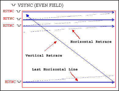
At an update rate of 30 frames/sec, the human eye can perceive a flicker as the screen is updated. To minimize this phenomenon, interlaced scanning is typically used. Here, the image frame is split into two fields, one containing odd-numbered horizontal lines and the other containing the even-numbered lines. Then the display is updated one field at a time at a rate of 60 fields/sec. This update rate is not detectable by the human eye (remember AC lighting operates at 60 Hz). Cameras that output interlaced video signals are usually referred to as area scan cameras.
For some high-speed applications, you want the display to update as rapidly as possible to detect or measure movement accurately. In that case, you might want to update the display without combining the odd and even fields into each frame. The resulting image frames would each consist of one field, resulting in an image with half the height and twice the update rate as the interlaced version. This is called non-interlaced video, and cameras that output signals of this type are referred to as progressive scan cameras.
Line scan cameras are a third type; they output one horizontal video line at a time. The frame grabber collects the lines and builds an image of a predetermined height in its onboard memory. A variation on this is a mode called variable height acquisition (VHA). In this mode, the frame grabber collects video lines into an image while another input signal remains active. When the signal becomes inactive, the resulting image is transferred to system memory. Line scan cameras are often used to image circular objects; for example, if you were to rotate a soda can in front of a line scan camera, you could obtain a flattened image of the entire surface of the can. Line scanning is also useful for conveyor belt applications, where parts are moving past a fixed camera. Often a detector is used to provide a trigger signal to begin the acquisition when the object reaches the camera. In the VHA mode, a second detector can be used to signal the end of the object, terminating the acquisition. This is extremely useful for applications in which the objects to be imaged are of variable or unknown lengths.
See Also:
Conveyor Belt Applications
Analog Video Signals
An analog video signal consists of a low-voltage signal containing the intensity information for each line, in combination with timing information that ensures the display device remains synchronized with the signal. The signal for a single horizontal video line consists of a horizontal sync signal, back porch, active pixel region, and front porch, as shown below:
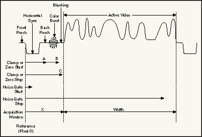
The horizontal sync (HSYNC) signals the beginning of each new video line. It is followed by a back porch, which is used as a reference level to remove any DC components from the floating (AC-coupled) video signal. This is accomplished during the clamping interval for monochrome signals, and takes place on the back porch. For composite color signals, the clamping occurs during the horizontal sync pulse, because most of the back porch is used for the color burst, which provides information for decoding the color content of the signal. There is a good description for all the advanced set-up parameters for the video signal in the on-line help for the Measurement & Automation Explorer.
Color information can be included along with the monochrome video signal (NTSC and PAL are common standard formats). A composite color signal consists of the standard monochrome signal (RS-170 or CCIR) with the following components added:
- Color burst: Located on the back porch, it is a high-frequency region which provides a phase and amplitude reference for the subsequent color information.
- Chroma signal: This is the actual color information. It consists of two quadrature components modulated on to a carrier at the color burst frequency. The phase and amplitude of these components determine the color content at each pixel.
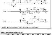
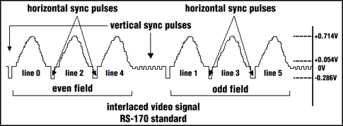
Another aspect of the video signal is the vertical sync (VSYNC) pulse. This is actually a series of pulses that occur between fields to signal the monitor to peform a vertical retrace and prepare to scan the next field. There are several lines between each field which contain no active video information. Some contain only HSYNC pulses, while several others contain a series of equalizing and VSYNC pulses. These pulses were defined in the early days of broadcast television and have been part of the standard ever since, although newer hardware technology has eliminated the need for some of the extra pulses. A composite RS-170 interlaced signal is shown below, including the vertical sync pulses. For simplicity, a 6-line frame is shown:
It is important to realize that the horizontal size (in pixels) of an image obtained from an analog camera is determined by the rate at which the frame grabber samples each horizontal video line. That rate, in turn, is determined by the vertical line rate and the architecture of the camera. The structure of the camera's CCD array determines the size of each pixel. In order to avoid distorting the image, you must sample in the horizontal direction at a rate that chops the horizontal active video region into the correct number of pixels. An example with numbers from the RS-170 standard:
Parameters of interest:
- # of lines/frame: 525 (this includes 485 lines for display; the rest are VSYNC lines for each of the two fields)
- line frequency: 15.734 kHz
- line duration: 63.556 microsec
- active horizontal duration: 52.66 microsec
- # active pixels/line: 640
Now, some calculations we can make:
- Pixel clock (PCLK) frequency (the frequency at which each pixel arrives at the frame grabber):
640 pixels/line / 52.66 e-6 sec/line = 12.15 e6 pixels/sec (12.15 MHz) - Total line length in pixels of active video + timing information (referred to as HCOUNT):
63.556 e-6 sec * 12.15 e6 pixels/sec = 772 pixels/line - Frame rate:
15.734 e3 lines/sec / 525 lines/frame = 30 frames/secAnalog Standards
|
Format |
Country |
Mode |
Signal Name |
Frame Rate (frame/sec) |
Vertical Line Resolution |
Line Rate (lines/sec) |
Image Size (WxH) pixels |
| NTSC | US, Japan | Mono | RS-170 | 30 | 525 | 15,750 | 640x480 |
| Color | NTSC Color | 29.97 | 525 | 15,734 | |||
| PAL | Europe (except France) | Mono | CCIR | 25 | 405 | 10,125 | 768x576 |
| Color | PAL Color | 25 | 625 | 15,625 | |||
| SECAM | France, Eastern Europe | Mono | 25 | 819 | 20,475 | N/A | |
| Color | 25 | 625 | 15,625 |
- High spatial resolution (larger images)
- High intensity resolution (bit depth)
- High speed
- Flexibility in timing or scanning characteristics
- Noise immunity
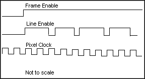
The timing signals for digital video are much simpler than those for analog video, since the signal is already digitized. They include a pixel clock, which times the data transfer and can be an input to or output from the camera; a line enable to signal the beginning and end of each video data line; and a frame enable to signal the start and completion of each frame:
These signals, as well as the data itself, can be single-ended (TTL) or differential (RS-422 or LVDS).
There is no standard scanning pattern for digital video signals, so the digital frame grabber needs to be configurable in order to be compatible with all the different scanning conventions available. One important factor in the type of scan is the number of taps a camera has. Some cameras can output two, four, or more pixels in parallel. For example, a 32-bit frame grabber (having 32 data I/O lines) is capable of reading four 8-bit pixels simultaneously. So, the frame grabber needs to be configured to place those four pixels in the proper portion of the image. The camera documentation specifies the exact order in which the image data will be delivered to the frame grabber.
Reader Comments | Submit a comment »
Nice intro
- Nov 29, 2007
Not clear description
I found Front porch and Back porch definitions not clear to satisfy the reader. Please modify these to reflect more clearance in the document. Rest of document is excellently written. Thanx
- Ravi Thakur, Barco Electronics P ltd, noida. geek_comp@yahoo.com - Dec 25, 2005
very good informations , i was looking for this infos , very useful for video engineer
- Oct 5, 2005
GENERAL COMMENT: exactly the thing i wanted to know to start my LAser beamer Project
i was curious if it is posible and effective to build a laserbeamer using VGA D-SUB15 output and i think it must be easy since you only need 3 Lasers(R,G,B G & B are most expensive but maybe some cheap things are there) and 2 moresided(depending on motorspeed and accuracy at least 6 sided ) mirrors and two motors and two and a reed contact or something else tomake the motor stop till hsync or vsync comes and a few electronic components to adjust laser intensity and "starting"(optimal would no stopping be) the turning of the mirrors again
- Nov 19, 2004
No circuits, no explanation No software No signal flowing shown out
- TERRY, AAFS ENGINEERING (M) Sdn bhd. terry@alhq.com.my - Jun 30, 2004
Legal
This tutorial (this "tutorial") was developed by National Instruments ("NI"). Although technical support of this tutorial may be made available by National Instruments, the content in this tutorial may not be completely tested and verified, and NI does not guarantee its quality in any way or that NI will continue to support this content with each new revision of related products and drivers. THIS TUTORIAL IS PROVIDED "AS IS" WITHOUT WARRANTY OF ANY KIND AND SUBJECT TO CERTAIN RESTRICTIONS AS MORE SPECIFICALLY SET FORTH IN NI.COM'S TERMS OF USE (http://ni.com/legal/termsofuse/unitedstates/us/).
'Research > Broadcast' 카테고리의 다른 글
| How to extract DTS/PTS values out of MPEG-2 PES header (0) | 2009.01.30 |
|---|---|
| 채널 적응형 위성방송을 위한 DVB-S2 기술동향 (0) | 2008.03.28 |
| YPbPr, RGB, Composite and S-VIdeo Colorbars (0) | 2008.02.19 |
| what's Es/No mean? (0) | 2007.12.31 |
| MPEG-2 4:2:2 (0) | 2007.12.28 |